
.png)
How it works in 8 easy steps

The MicroLoc system is know for it’s simplicity. The MicroLoc® Workholding system can be configured to a CAD/CAM application for optimum layout of workpieces, whilst the Reference Base datum intersections contribute to ease of programming. Large bases may be fixed permanently to machine tables, encompassing a wide range of applications. Its simple to use and quick to change
Also available as a PDF


01
STEP 01
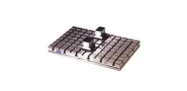
Mount the Baseplate
Mount the baseplate to your machine table t-slots using a pair of adaptor tenons fitted to key recesses in the underside of the MicroLoc® baseplate.

Complete Process Overview

01
Mount the Baseplate
Mount the baseplate to your machine table t-slots using a pair of adaptor tenons fitted to key recesses in the underside of the MicroLoc® baseplate.
02
Insert Locators
Insert locators carefully into the desired positions on the baseplate.

03
Slide in Sideclamps
Slide in sideclamps and tighten to secure the setup.

04
Position Clamping Jaws
Position clamping jaws by placing a loose rack into cross-slots in the baseplate.

05
Engage the Rack
Using a component as a template, engage the rack in the underside of the clamping jaw into the loose rack to locate the component within 3mm.

06
Adjust Sliding Jaw
Each side of a clamping unit has a sliding jaw with a stroke in excess of 3mm. Slide in sideclamps and tighten.

07
Fit End-stops
Determine by inspection the number of end-stops and spacers to be fitted.
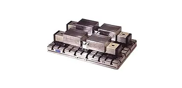
08
Load Components
Load the components and tighten using the central actuating screw.

